N+1 CONTROL SYSTEM
Changeover
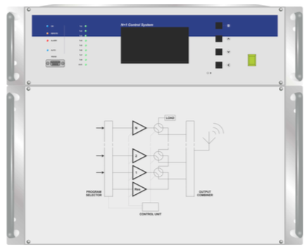
The N+1 Control System acts as a N+1 passive reserve controller. Monitoring continuously the correct operating state of a transmitting equipment allows to detect possible failures, and automatically replacing it with a reserve transmitter if needed. In a N+1 system the reserve transmitter is shared among N transmitters. If the fault transmitters are more that one the N+1 system decide, based on a prearranged priority, which is the transmitter replaced by reserve one. The detection of the correct working status of the transmitters is made on output power reading of transmitters. The operational parameters of the system, such as 0dB power level, intervention threshold, switching time of the transmitters, manual or automatic working mode, can be configured by display and keys user interface. Just the large display and a series of bicolour led allow a very quick view of the system state. The system can be remotely controlled via serial (RS232 or RS485) or parallel connection. It is composed by two sections: the control unit and the base-band signal switch and distribution section. The former section monitors the operating status of the N+1 transmitters, checks the position of the external coaxial relays and the operation of the dummy load, if any. The second section switches the base-band signals (audio and/or video) and the RDS 19kHz pilot tone signal in case of FM transmitters (useful if there is an external encoder). The switch section is also a distribution section, so as to allow to the transmitter on dummy load to input the desired base-band signal. It is possible to switch on the transmitter on dummy load for test purpose. If squelch occurs on transmitters the N+1 switch is inhibited by a dedicated signalling. The switch on and off of transmitters is made by free contact.